Networking and the Internet
To understand the role of the browser in Internet privacy, it is helpful to have a basic understanding of how networks function. In its most basic form, a computer network is simply what we get whenever two or more computers are connected to each other using hardware that allows messages to be exchanged. There are numerous different kinds of network hardware in widespread use, including wired Ethernet, wireless Ethernet (or WiFi), and fiber optic. Back in the days of dialup Internet connections, computers communicated using sound signals transmitted over a telephone line. Researchers are constantly working on new connectivity systems using a wide variety of different media (light, sound, radio, etc.).
Video Lecture
Network Protocols
While the simplest definition of a network involves connecting a few computers together and letting them communicate with each other, there are some additional moving parts that have to be implemented correctly in order for the communication to work properly. In particular, some rules need to be established to define how this communication will occur. At the hardware level, we need to know what each kind of physical signal means for each different kind of network device. For an electrical device, we need rules to say what different voltage levels mean. An optical device needs similar kinds of rules: what does a given pulse of light mean? Radio waves and other signals also need rules to establish relationships between the signals and their meanings.
Once we have the hardware rules in place to be able to send a signal between two computers at the physical level, we need some software rules to explain the data format needed to make sense of messages at each end of the connection. Computers are machines and are not sentient beings: they cannot automatically tell the difference between one kind of data and another or figure out where a message starts and stops like our human brains can. Therefore, our rules about how we communicate need to be specified precisely so that engineers and software developers can implement them properly and test for correct operation.
We call these hardware and software rules network protocols. A network protocol defines the way that two computers will talk to each other. While we could implement a single network protocol that could handle both the physical communication rules and the software rules, such a protocol would be unwieldy to implement and would only allow two of the exact same kinds of computers with the same network hardware and the same software to communicate with each other. Early in the days of networking, it was discovered that breaking the network protocol into different layers made understanding the entire system much easier while also making it possible for devices made by different manufacturers to “speak” the same protocols and therefore interoperate. A working network application requires using protocols from several layers, with the entire higher-layer protocol packed into the protocol of the layer beneath it. We call this arrangement of multiple protocols a protocol stack.
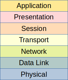
One key conceptual model that describes how protocols can be broken into layers is the Open Systems Interconnection (OSI) model.1 In the OSI model, the network is divided into seven layers as illustrated in Figure 1. We number these layers from the bottom, starting with the Physical Layer at layer 1. Thus, the order of layers in the OSI model is Physical, Data Link, Network, Transport, Session, Presentation, and Application.
The Physical Layer (layer 1) is the lowest layer in the OSI model. In this layer, electrical, fiber optic, radio, or other physical signals are described for interconnecting devices that use the same kind of physical medium. Protocols at this layer are designed to transmit and receive a stream of bits (0s and 1s). A Physical Layer protocol receives a stream of bits from the Data Link layer above it and converts those bits into physical signals. Physical signals received at layer 1 are converted back into a stream of bits to send to the Data Link layer.
The Data Link Layer (layer 2) splits the stream of bits into chunks called frames. A frame is the Protocol Data Unit (PDU) of the Data Link Layer. Frames permit individual messages to be directed to specific computer systems that are directly connected to a shared physical layer, or network segment. In order to perform this function, frames implement a hardware-level addressing scheme. Since the stream of bits received from the physical layer is not always perfect and may contain a few small errors, frames also provide ways to perform some basic bit-level error detection and correction.
As the number of devices in a network grows larger, it becomes impractical to connect them all in a single network segment due to increased cost and complexity of the physical layer and decreased performance resulting from communications collisions. Instead, individual network segments are joined together by a computer that has a separate physical connection to each segment. This computer receives messages from one segment and forwards them to another segment, in a process called routing (the computer doing the routing is called a router). Routing is a major function of the third layer of the OSI model: the Network Layer. The typical Protocol Data Unit (PDU) for this layer is the packet, which is a data structures that contains both a message and some addressing information that enables a router to send the message across one or more network segments (a process called a hop).
When networks become sufficiently large and contain multiple hops, the potential exists for packets to be routed in ways that could cause messages to arrive out-of-order. Sometimes a packet might also be transmitted more than once, resulting in duplicate copies of the same packet arriving at the destination. If a router gets overloaded, it might drop, or discard, one or more packets. For these reasons, it is convenient to have network protocols that can manage data flows, fix out-of-order reception, and de-duplicate packets. These protocols are implemented at layer 4, which is the Transport Layer. Two major types of Transport Layer protocols are used: reliable protocols, such as the Transmission Control Protocol (TCP),2 automatically confirm receipt of the message at the other end of the connection and can optionally retransmit lost packets. On the other hand, unreliable protocols like the User Datagram Protocol (UDP)3 work using more of a “fire-and-forget” approach with no confirmation or retransmission.
In practice, modern network systems typically do not use layers 5 and 6: the Session Layer and the Presentation Layer. The concept behind the Session Layer is that it would establish, close, and manage connections using a transport-layer protocol. While some remote procedure call implementations have a Session layer, it is not widely used, and most applications perform their own session management. Similarly, the OSI model defines the Presentation Layer as a protocol to translate between the application’s internal data representation and a network data flow. The application programmer normally ends up handling this task by writing network interface code that is specific to the application.
Finally, the top layer of the protocol stack is the Application Layer, which is layer 7 in the OSI model. Depending on the context of the conversation, the application itself can be described as being part of this layer. Applications can utilize standard, commodity layer 7 protocols like HTTP or DNS by including libraries that implement these protocols. Alternatively, applications can define completely custom protocols at layer 7, in which case the application will only be able to communicate with other copies of itself or other applications that are designed to use that same custom protocol.
Addressing
In order for messages to be sent to destinations, each device on the network has to be assigned a unique address. Most of the time, two such addresses are assigned: one each at the Data Link and Network layers. For a typical network, the layer 2 address is the Media Access Control (MAC) address. This address has a format of 6 octets (bytes) expressed in hexadecimal (base 16, using the digits 0-9 and letters a-f). An example of a MAC address is f2:12:34:56:78:9a. Most network devices, including network interface cards, wireless adapters, and cable modems, have a MAC address that is assigned from the factory. However, it is possible to assign a different MAC address to most kinds of devices.
In contrast, the typical Network Layer address used in modern networks is the Internet Protocol (IP) address. These addresses are hardware-independent and are usually assigned either by some automatic method (such as autoconfiguration or the Dynamic Host Configuration Protocol – DHCP) or manually by a system or network administrator. Two versions of the Internet Protocol are currently in use, so there are two kinds of IP addresses that may be encountered. The older type of address is the IP version 4 (IPv4) address from the older version of the Internet Protocol.4 These types of addresses are expressed in dotted decimal notation and have a format like 192.0.2.5. Devices using the newer version of the Internet Protocol have an IP version 6 (IPv6) address.5 These addresses are much longer and are expressed in hexadecimal. A lengthy example is 2001:0db8:1234:5678:90ab:cdef:1234:5678, although many addresses can be written in a compact form by leaving out leading zeros and groups of zeroes. The IPv6 loopback address, which refers to the local machine itself, can be written as ::1 when shortened. Since the two versions of the Internet Protocol can coexist on the same network, it is not uncommon for a network adapter to have both an IPv4 and an IPv6 address.
Addresses and Privacy
There are some significant privacy concerns related to the addresses a computer has, including the MAC addresses of all its network adapters and the IPv4 and IPv6 addresses assigned to it. First, most MAC addresses are assigned by the network device manufacturer. To ensure that equipment purchased from different manufacturers will not have duplicate addresses when deployed on the same network segment, manufacturers assign the first 3 octets of the address to a unique identifier that is assigned to each company.6 Since the MAC address doesn’t normally change after assignment, a standard technique in digital forensics is to catalog the MAC addresses of each network adapter in a system under investigation, which might permit the association of network traffic with a particular machine (and therefore with an individual person).
One additional concern with MAC addresses is related to computer security. If it is known that a particular kind of network adapter has an exploitable security flaw, then attacks on that kind of device become easier to implement. An attacker could determine the brand of network device by looking up the first 3 octets of the address. Furthermore, some methods of automatically configuring IPv6 addresses leak the MAC address to a potentially global audience by using the MAC address as part of the IPv6 address.7
While IPv4 and IPv6 addresses assigned to a single computer can change over time, particularly if they are assigned using an automatic method, some entity is ultimately responsible for the assignment. This entity is typically an Internet Service Provider (ISP), employer, university, or another organization with some centralized form of administration. These organizations normally maintain records linking users to IP addresses (a procedure mandated by law in places). Therefore, identifying an individual from an IP address is often possible.
Even when addresses are automatically assigned and change periodically, the frequency at which they change is typically relatively slow (on the order of multiple hours or days). IP addresses can therefore be used as a component in tracking and fingerprinting users. For all these reasons, Europe generally considers an IP address to be a type of personal data that can be used to identify an individual.8
Internetworking
An internetwork is a large network composed of multiple independent networks. These independent networks share a common Network Layer (layer 3) protocol, making it possible for a heterogeneous mixture of different kinds of hardware to communicate at a wide scale, even when different networks use different layer 1 and 2 protocols. Each network in an internetwork can potentially be owned by a different entity. As long as no firewalls prohibit communication, computers in one network can communicate with those in another network using the layer 3 addresses. A single internetwork is usually shortened to an internet, with a lowercase i.
The worldwide system called The Internet (with an uppercase I) is a giant internetwork that spans the globe. The Internet uses the Internet Protocol (IP) as the common Network Layer that enables communication between any two systems worldwide. Before it was fully commercialized in 1995, our modern Internet evolved from a Department of Defense network originally known as ARPANet, dating all the way back to 1969.9
Client-Server Model
When networking and programming come together to create a typical Internet application, a commonly used design paradigm is the client-server model. In a client-server design, two computer programs talk to one another over a network in such a way that one program requests things from the other program. Each program is usually running on a separate computer system. The two kinds of programs are defined as follows:
- Client
- The program that makes requests.
- Server
- The program that listens for requests, handles them, and returns responses to the client.
We also use the terms client and server to refer to the two computer systems involved in this type of communication. The context of the conversation determines whether we’re talking about a client or server program versus a client or server machine. One way to remember the distinction between clients and servers on the Internet is that the server provides the service, while the client accesses that service. Examples of services include Web pages, email services, and instant messaging systems. Clients that can connect to those services include Web browsers, email programs, and instant messaging apps.
References and Further Reading
-
Jack Houldsworth. “Standards for open-network operation.” ICL Technical Journal 1(1): 50-65. November 1978. Available from Fujitsu. ↩
-
Wesley Eddy. “Transmission Control Protocol (TCP).” RFC 9293. August 2022. ↩
-
Jon Postel. “User Datagram Protocol.” RFC 768. August 1980. ↩
-
University of Southern California Information Sciences Institute. “Internet Protocol: DARPA Internet Program Protocol Specification.” RFC 791. September 1981. ↩
-
Steve E. Deering and Bob Hinden. “Internet Protocol, Version 6 (IPv6) Specification.” RFC 8200. July 2017. ↩
-
Robert Hinden and Stephen Deering. “IP Version 6 Addressing Architecture.” RFC 2373. July 1998. ↩
-
Judgment of 19 October 2016, Patrick Breyer v. Bundesrepublik Deutschland, C-582/14. EU:C:2016:779. ↩
-
The Living Internet. “Internet History – One Page Summary.” ↩
