Storage Devices
Mass storage devices, also known as block devices, are pieces of hardware that store data. These devices are collectively the primary source of digital evidence in a forensic investigation. In order to access this evidence, the forensic lab must have the necessary equipment to read data from a variety of different devices.
Video Lecture
Block Devices
Mass storage devices provide persistent storage of data, meaning that the data are not erased whenever the computer system is turned off. For efficiency reasons, these devices typically access fixed-size chunks, or blocks, of data at a time. Traditionally, blocks of data on a hard disk drive were 512 bytes in size. However, many newer hard drives, and nearly all solid state drives, use block sizes of 4 KiB (or even 8 KiB on some larger devices). Since data can only be read and written in units of blocks, another name for a mass storage device is a block device.
Types of block devices include:
- Hard disk drives (HDDs).
- Solid state drives (SSDs).
- CD-ROM/DVD-ROM/Blu-ray discs (optical discs). Most types of optical discs are read-only (Read-Only Memory, or ROM). However, CD-R, DVD-R, DVD+R, DVD-RW, and DVD+RW, as well as certain types of Blu-ray disc, are writable by the user. The -R variants are only writable one time, while the RW variants can be erased and rewritten multiple times.
- Portable devices that act like drives, including digital cameras, video games, GPS units, and other consumer electronics (including toys).
- Flash storage devices, including USB flash drives, Secure Digital (SD) cards, embedded MultiMediaCard (eMMC) devices, Compact Flash (CF) cards, proprietary storage cartridges, and various other types of flash storage.
Device Attachment
Attaching a block device to a system requires two parts: the physical connection between the block device and the computer’s motherboard, and the communication protocol used to transfer data over the physical connection. The physical connection can be made in a number of different ways, using a cable, port, slot, or connector of some type. Additionally, storage devices may be permanently soldered onto the motherboard or main logic board of a computer or other devices.
The processor or microcontroller in the computer or electronic device communicates with the block device using some type of data transfer protocol, which is a disciplined way of exchanging messages. A variety of such protocols exist, including ATA, SCSI, USB, and SPI, among many others. To make matters more confusing, sometimes the protocol name (for example, ATA) overlaps with the connector name (ATA, SATA, or PATA). However, the protocol does not necessarily require a particular connector. In theory, any data exchange protocol can be used with any physical connection method. Therefore, it is necessary to ensure that the forensic lab workstation that will be used for evidence acquisition has both the proper physical connection type and the proper connection driver for the block device that will be imaged.
Physical Attachment
Cables
USB
The Universal Serial Bus (USB) cable is a common physical connection method for external devices, such as external hard drives and consumer electronics devices. While USB cables are primarily used for external devices, it is possible for a computer or other system to be constructed with an internal USB cable or connector that links a block device to the main processing component of the system. Some connectors, such as mini PCI Express connectors in a laptop, may have USB data lines as part of the connector. A device plugged into such a connector might have a USB connection, even though it does not use an obvious USB cable.
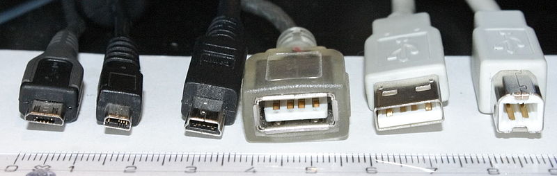
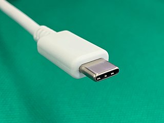
Figure 1 shows an assortment of different USB connectors for different types of devices. After a proliferation of connector types, the standards body finally decided that a single universal connector type would be an improvement, leading to the USB type C cable (Figure 2).
Serial ATA (SATA)
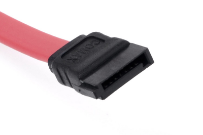
The Serial Advanced Technology Attachment (SATA) cable (Figure 3) is currently the standard way of connecting mechanical hard drives, and larger form factor solid state drives, to computer motherboards in consumer systems. This type of cable evolved from the original “advanced technology” cables, which were originally designed for the IBM PC/AT, released in 1984.
IDE/Parallel ATA (PATA)
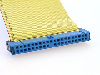
Before the invention of the SATA connector, consumer computer systems used a wide, flat ribbon cable to connect hard drives to the motherboard. The original form of this cable was the Integrated Drive Electronics (IDE) cable, which used a 40-pin connector at each end, with 40 wires carrying 40 lines of data. Updated versions of the cable, shown in Figure 4, used 80 wires to carry the 40 pins’ worth of data, changing the electrical properties of the cable (capacitive coupling) to enable faster transfer speeds. Once much faster SATA interfaces had been developed, this type of cable and connector was retroactively rebranded Parallel ATA, or PATA.
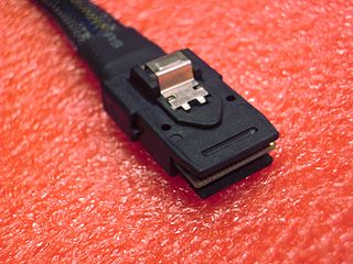
Serial Attached SCSI (SAS)
Serial Attached Small Computer System Interface (SAS) connectors and cables are uncommon on consumer computers. However, they are widely used on enterprise systems, such as servers. There are actually several different types of SAS cable available, including SFF-8087, SFF-8088, SFF-8470, SFF-8482 (which looks like a SATA cable), SFF-8484, SFF-8643, and SFF-8644. These cables may not immediately resemble one another at first glance. Figure 5 depicts an SFF-8087 cable.
SCSI
The Small Computer System Interface (SCSI, usually pronounced “scuzzy”) refers broadly to an entire set of cables and protocols. While this interface has fallen out of favor with the rise of SAS and Fibre Channel devices, parallel SCSI cables may still be found on ancient servers. These flat cables have 50, 68, or 80 pins, depending on the standard used. Close inspection, possibly counting the pins on the connector, may be necessary to differentiate a parallel SCSI cable from a PATA cable, since this type of connection is not as common as it used to be.
Ports, Slots, and Connectors
As the speeds of block devices continue to increase, the cables become problematic as sources of electrical interference. Thus, many newer devices are directly connected to the motherboard, sometimes using slots, sockets, or other connectors. Direct connections permit the radio frequency emissions of the data transfer lines to be controlled by keeping the connections short. Without this optimization, bulkier shielded cables would be needed to permit devices to operate at high speed.
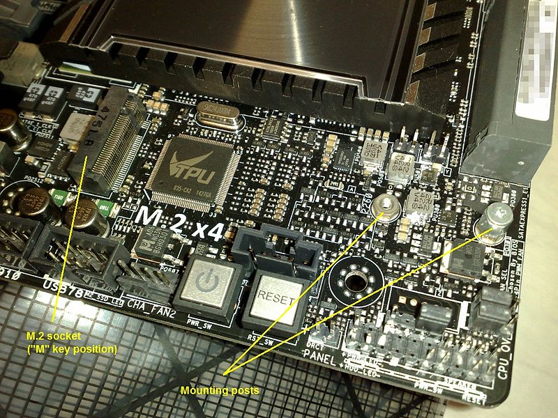
The M.2 form factor defines a standard size for an interface to solid state drives. Connectors using this form factor (Figure 6) are now common on laptop motherboards and are also available on desktop motherboards. M.2 connectors provide for extremely high speed connections for fast block storage devices.
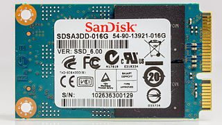
M.2 form factor devices arrived on the market relatively quickly following the first attempt at miniaturization, which used the mini-SATA (mSATA) form factor (Figure 7). While it is possible for a SATA SSD to use the M.2 form factor, M.2 is not compatible with mSATA. Therefore, if a user migrated from an older system using an mSATA SSD, it would be necessary to replace the SSD with a new one using the M.2 form factor.
Other card- and connector-based block devices may be used to store data. Among these are the Secure Digital (SD) card format (including the tiny MicroSD card) and the embedded MultiMediaCard (eMMC) format. SD cards are typically used in removable device applications, such as digital cameras. However, they may also be used as primary storage devices for single board computers, such as the Raspberry Pi8. Cell phones, low-end laptops, and some higher-end single board computers often use internal eMMC devices as primary storage.
Solder
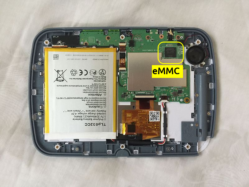
In many embedded applications, and in some lower-end laptop applications, the block storage device for a system might simply be soldered directly to the motherboard or main logic board. Soldering the storage in place reduces the costs associated with providing a socket and mounting hardware for a removable device. This style of connection is especially common in embedded systems, such as single board computers, cell phones, gaming devices, and consumer electronics devices. Figure 8 illustrates an eMMC directly soldered onto the main logic board of an educational toy designed for children.
Communications Protocols
Once a block storage devices has been connected to a system, the system must communicate with the block device in a disciplined way, passing messages back and forth in a predefined format. This format is called a protocol, and desktop computers have historically been dominated by two major ones: SCSI and ATA. Unfortunately, these two protocol names overlap with the names of connector and cable types, even though it is possible to implement either one using a variety of different physical connections.
The Small Computer System Interface (SCSI) protocol has been widely deployed in a variety of devices. In addition to SCSI disks, the protocol is used as the basis for optical drives using the ATA Packet Interface (ATAPI) protocol, which uses ATA cabling. Subsets of the SCSI protocol are widely used in USB devices.
Overlapping the SCSI protocol in many ways is the ATA protocol, which was originally used with PATA or IDE connections between the motherboard and the drive. Borrowing some ideas from SCSI, this protocol has been adapted for use with higher speed devices, including those using SATA connections. In practice, most SATA drives implement an updated version of this protocol, which is the Advanced Host Controller Interface (AHCI).
A recent (as of late 2020) substantial improvement to the protocol used by motherboards and SSDs is the Non-Volatile Memory Express (NVMe) interface. This protocol significantly reduces overhead and improves performance over the ATA and AHCI interfaces, permitting extremely fast SSDs. At this time, most SSDs using this protocol connect via the M.2 physical connector, but it is probable that more advanced connection methods will be invented with time.
At the other end of the performance spectrum is the Serial Peripheral Interface (SPI) protocol, which is frequently used with microcontrollers and other embedded devices. SPI is one choice of protocol for interfacing with SD cards, which is a reason why SD cards are popular as storage media on inexpensive consumer electronics devices. There is native SD/MMC protocol that offers much faster bus speeds than are achievable with SPI. This native protocol is used for eMMC devices as well as faster devices utilizing SD cards.
Practical Considerations
In digital forensics applications, the connectors and protocols are normally only a concern with respect to making a forensic image of the storage device. Esoteric cases may exist, in which the storage protocol itself becomes a subject of debate in court, but the primary concern for the investigator is image acquisition. Investigations of digital evidence (data) should always be conducted on images, or bit-by-bit copies, of the data. After images are created, the storage devices are securely retained in an evidence room, and all analysis is performed on the images. Conducting an investigation on an original block storage device risks damaging or changing the data, causing evidence spoliation that renders the results of the investigation inadmissible in court.
Prior to the image acquisition phase, it is important to recognize and acquire all storage devices in the discovery phase of a case. If a discovery order in a civil case demands all the hard drives used by a company, for example, the company would technically be in compliance with the order if it turned over all the mechanical hard drives but none of its SSDS.10 Similarly, upon investigating a crime scene with a search warrant, it is necessary to ensure that all storage devices present (and within the scope of the warrant) have been seized.
Notes and References
-
Image Credit: Viljo Viitanen (via Wikimedia Commons). License: Public Domain. ↩
-
Image Credit: Project Kei (via Wikimedia Commons). License: CC-BY-SA. ↩
-
Image Credit: Evan-Amos (via Wikimedia Commons). License: Public Domain. ↩
-
Image Credit: Jonas Bergsten (via Wikimedia Commons). License: Public Domain. ↩
-
Image Credit: GreyCat (via Wikimedia Commons). License: CC-BY-SA. ↩
-
Image Credit: Dsimic (via Wikimedia Commons). License: CC-BY-SA. ↩
-
Image Credit: Raimond Spekking (via Wikimedia Commons). License: CC-BY-SA. ↩
-
Image Credit: Blakegripling ph (via Wikimedia Commons). License: Public Domain. Modified to show location of eMMC. ↩
-
I am not a lawyer. A “hard drive” in computing terms does not include a solid state drive (SSD), as they are distinctly different devices. Whether or not this distinction is legally valid is a matter for the court to determine. ↩
