Circuits with Gates
By wiring multiple gates together, we can produce circuits that can accomplish useful tasks. Examples of such useful circuits at a relatively small scale include adders and comparators, which provide the building blocks for performing arithmetic. At a larger and more complex scale, circuits made from collections of gates implement major components of computer processors, such as the arithmetic and logic unit.
Video Lecture
True and False
When we’re using standard electrical logic within a circuit, we represent the value true, or 1, by connecting to positive voltage. A false value, or 0, is represented by connecting to negative voltage. In a standard circuit diagram, positive voltage is normally represented by the symbol VCC, which stands for voltage common collector. The negative side of our power supply is represented by GND, for ground.
Certain types of circuit diagrams might use alternate symbols for positive voltage, such as VBB or VDD. Some kinds of analog circuits might also be connected to an earth ground, in which case the symbols VEE or VSS might appear on a diagram. An electrical engineer should be consulted if troubleshooting a piece of equipment requires understanding a complex circuit.
Adding Gates
One convention we often use when describing electrical circuits is to give each input and output a distinct label. In simple cases, we can use letters for inputs, such as A, B, C, and D. If a circuit has a single output, we often label that output with the letter Q. Circuits that produce multiple outputs can be labelled with subscripts, such as Q0, Q1, Q2, and so forth.
We construct circuits using wires to connect the various input and output pins on each gate. Individual gates form the building blocks of more complex circuits, which in turn can be wired into other circuits.
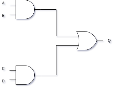
In Figure 1, we have the circuit that represents (A AND B) or (C AND D). This circuit’s output Q will be turned on whenever both inputs A and B are turned on, or whenever both inputs C and D are turned on, or whenever all 4 inputs are turned on. Table 1 shows the truth table for this particular circuit.
| A | B | C | D | Q |
|---|---|---|---|---|
| 0 | 0 | 0 | 0 | 0 |
| 0 | 0 | 0 | 1 | 0 |
| 0 | 0 | 1 | 0 | 0 |
| 0 | 0 | 1 | 1 | 1 |
| 0 | 1 | 0 | 0 | 0 |
| 0 | 1 | 0 | 1 | 0 |
| 0 | 1 | 1 | 0 | 0 |
| 0 | 1 | 1 | 1 | 1 |
| 1 | 0 | 0 | 0 | 0 |
| 1 | 0 | 0 | 1 | 0 |
| 1 | 0 | 1 | 0 | 0 |
| 1 | 0 | 1 | 1 | 1 |
| 1 | 1 | 0 | 0 | 1 |
| 1 | 1 | 0 | 1 | 1 |
| 1 | 1 | 1 | 0 | 1 |
| 1 | 1 | 1 | 1 | 1 |
Tracing the Circuit
To construct the truth table shown in Table 1, we first write down the inputs. The rightmost input alternates 0 and 1, starting from 0. Each input to the left of the rightmost one starts from 0 but alternates in a pattern that doubles the number of 0s and 1s in the column to the right of it.
In our case, column D is the rightmost input column, so it alternates 0, 1, 0, 1, 0, 1, 0, 1, and so on. Input column C is one place to the left of D, so it alternates with two zeroes and two ones, like so: 0, 0, 1, 1, 0, 0, 1, 1, .... Input column B is one place to the left of C, so it alternates with four zeroes and then four ones: 0, 0, 0, 0, 1, 1, 1, 1, 0, 0, 0, 0, 1, 1, 1, 1. Our final input column is A, which doubles the pattern from column B: eight zeroes, then eight ones. 0, 0, 0, 0, 0, 0, 0, 0, 1, 1, 1, 1, 1, 1, 1, 1.
To get the output column, we trace the circuit for each input column. Starting from the top row, all inputs are 0. A=0 AND B=0 yields 0 from the first AND gate. C=0 AND D=0 yields 0 from the second AND gate. The two inputs to the OR gate are therefore 0, and the resulting output Q is 0.
We get our first output of 1 when we reach the fourth row of the table. Since C and D are both 1, the output of the second AND gate is 1. If either input to an OR gate is 1, then the output of that gate will be 1. In this case, the output of the OR gate is the output of our circuit.
Any logical circuit can be traced using this approach. While it is tedious, the only sure way to perform a trace is to follow each combination of inputs through the circuit to figure out what the output will be. Fortunately, this process only has to be done once for any given circuit… that is, as long as you remember to save the truth table somewhere!
