Switches and Gates
An electronic computer system is really a giant collection of digital switches, which are turned on and off in order to make the computer function. Each of these switches has two discrete states: it is either on or off, with no state in between. For this reason, we refer to the system as a digital computer.
The opposite of two discrete states would be for a switch to have a range of values, like a dimmer switch at your dining room table or controlling the instrument panel lights in your car. We refer to this other type of control as analog, since it is infinitely adjustable within some range. While analog computers have been built, and some still see use in older aerospace and military applications, we will be focusing on digital computers for our study of computer architecture. By far, digital computers are more common, and they are the type of system used in your laptop, cell phone, smart TV, home network router, and countless other devices.
Video Lecture
Use of Switches
In general, a low-level digital electronic component within a computer is in one of two states: on or off. The simplest method for turning a component on or off would be to connect or disconnect electrical power. When operated manually, connection and disconnection would involve attaching or removing wires from the component. This process is tedious, hard on the connectors, and is prone to accidental short circuits. For these reasons, we normally use a switch to control power to individual components.
We can use a switch to convey information. For example, we could turn on a switch to indicate that lunch is ready (Figure 1). If the switch connects to some type of circuit with an output, such as a light or buzzer, activating the switch would cause light or sound as a side effect. This output might then be used to notify others about the status of lunch.
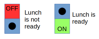
If we were limited to one switch, we could only convey two states, or different combinations of settings. In this example, the two available states would be “Lunch is not ready” and “Lunch is ready.” We can add extra states by adding more switches, but our efficiency will be better with a little bit of planning. For example, if we wanted to add information about which meal is being served, we could add two more switches to our system: one for breakfast, and one for supper. The chef would then activate the proper switch to indicate that the given meal was ready.
It turns out that such a naive approach would actually cause us to have one more switch than we actually need for this job. Since each switch costs money, and each connected piece of circuitry uses electricity (which also costs money), it is advantageous to find a way to represent information using the fewest number of switches possible. In this example, we can design our system to require only two switches with a little bit of planning (Figure 2).

We can convey more information using two switches in this case by having one of the switches represent breakfast. The other switch indicates whether or not lunch is ready. When it’s time for supper, the chef turns on both switches. With this little bit of planning, we can save 33% on our upfront hardware costs.
Electromechanical Switches
To implement a computer system, we cannot have the human operator responsible for turning on and off all the switches, one at a time. All the processing would be occurring in the operator’s brain, and the resulting system would not be the programmable, practical machine that we have come to expect. Therefore, we have to find a way to make it so that the machine can turn its own switches on and off in response to electrical signals inside it.
The first step toward a computer is therefore to find a way to make the switches turn on and off using electrical signals, instead of requiring a human operator. One early solution is to use an electromagnet in place of the operator. Whenever the electromagnet has power, it will move the switch and activate the circuit. Whenever power is turned off to the electromagnet, a spring attached to the other end of the switching mechanism will return the switch to its original position. This configuration is called a relay and is shown in Figure 3.

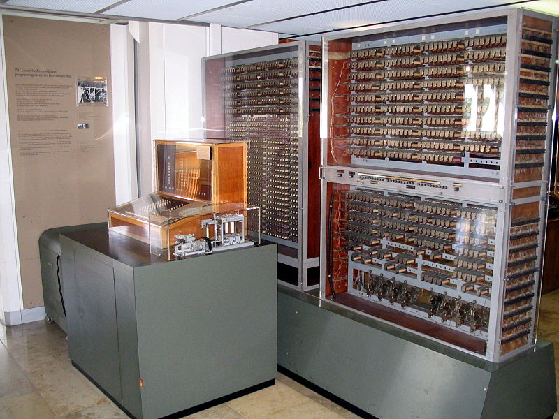
Relays are mechanical contraptions and are therefore prone to breakdowns. They are also relatively slow (exceptionally slow by today’s computer standards). However, relays, spinning wheels, and other mechanical components were used in some of the earliest computers around the time of World War II. These systems were electromechanical computers, in which electricity was used to move hardware devices that represented system state. Figure 4 shows a replica of such a system: the German Zuse Z3 from 1941.2
Vacuum Tubes
One of the first improvements over electromagnetic switches came in the form of triode vacuum tubes. A vacuum tube resembled an old-fashioned incandescent light bulb, in the sense that it contained electrical components inside a glass enclosure that had all the air removed from it. Vacuum tubes were originally used as amplifiers, enabling (among other things) louder radio receivers and record players.
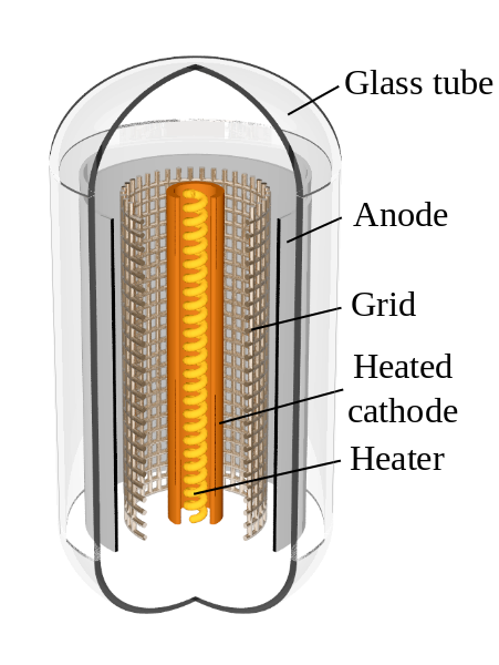
As shown in Figure 5, a vacuum tube consists of a heated cathode surrounded by an anode. Electricity flows in one direction from the heated cathode to the anode, as a result of vaporization of atoms from the cathode. The first such tubes were diode tubes and were used only to control the direction of current flow. An improvement to the diode tubes added a control grid between the cathode and anode, creating a triode tube. With a triode tube, a relatively small amount of voltage could be used to control a much larger one, making these devices especially suited for use in amplifiers.
The switching ability of triode tubes also made them useful in early computers, despite the fact that they could be less reliable than a relay. Although prone to burning out, tubes were significantly faster than relays, enabling faster systems to be built. The Electronic Numerical Integrator and Computer (ENIAC) was a prime early example, containing 17,468 tubes.5
Transistors
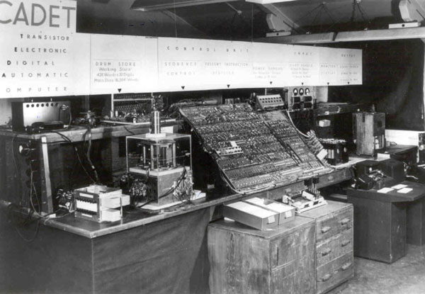
Invented in 1947, the transistor is a solid-state device that implements digital switching efficiently. Unlike the vacuum tube, the transistor does not require heating or changing anything from solid to gas (hence, the “solid” state). Consequently, transistors use far less electric power than vacuum tubes, and they are extremely reliable and long-lasting. One of the earliest transistor-based computers, the Harwell Cadet (Figure 6), appeared in 1951. This was followed by the IBM 608 in 1955.
Today, all general purpose computers use transistors as their digital switches. The vacuum tube has been relegated to niche applications, such as retro-style tube-amplified stereo systems and power amplifiers (klystrons) for radar systems and high-power Ultra High Frequency (UHF) transmitters. Relays are still widely used in numerous applications, including high-current switches in automotive systems and household appliances. However, modern computer systems are no longer electromechanical in design, except for hard disk drives and tape drives.
Logic Gates
By combining digital switches with other components, circuits can be designed to switch on or off based on logical conditions. Such circuits are called logic gates and are the building blocks of more complex circuits that perform computation. There are a number of logic gates, including AND, OR, NOT, NAND, NOR, XOR, and XNOR. The simplest of these, NOT, just inverts the logic. Thus, if we hook a single switch to a NOT gate, the output of the gate will be on whenever the switch is off, and off whenever the switch is on. See Table 1 for the behavior of the other gates.
| A | B | A AND B | A OR B | A NAND B | A NOR B | A XOR B | A XNOR B |
|---|---|---|---|---|---|---|---|
| off | off | off | off | on | on | off | on |
| off | on | off | on | on | off | on | off |
| on | off | off | on | on | off | on | off |
| on | on | on | on | off | off | off | on |
More advanced logical circuits are created by connecting the outputs of gates to the inputs of other gates. Complex circuits, including adders, can be built this way. Two of the gate types, NAND and NOR, are considered to be universal gates. Any other type of logic gate can be built using only NAND gates. Alternatively, any other type of gate can be built using only NOR gates. For this reason, you will often see computer hardware documentation refer to NAND or NOR logic, particularly when discussing solid-state storage devices.
Integrated Circuits
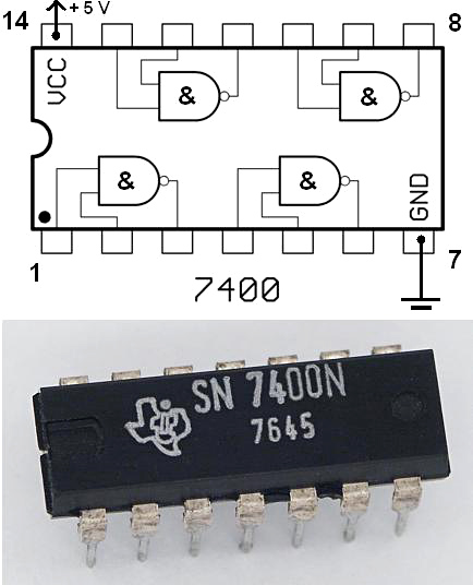
Improved manufacturing techniques permit multiple entire circuits to be embedded into small components called microchips. These devices are created using specialized techniques, using silicon and other raw ingredients to implement transistors and other electronic components, connecting them together at a microscopic level to create integrated circuits (ICs). Figure 7 illustrates a simple example of a microchip that implements 4 NAND gates.
Microchips have enabled powerful computation to fit into tiny form factors. For example, your cell phone is several orders of magnitude more powerful than the ENIAC, yet it fits into your pocket and can run for several days without needing to be charged. The ENIAC weighed over 27 tons, required a dedicated facility with 1,800 square feet of space, and consumed around 150 kW of power when operating.5 For reference, a typical modern house with most appliances running at the same time will consume around 20 kW.
Magic White Smoke
So far, we have discussed digital switching systems in terms of moving electricity around inside circuits. However, in practice, modern integrated circuits are designed to move magic white smoke around between themselves and externally connected circuits. To prove this, all we need to do is reverse the positive and negative connections on the chip shown in Figure 7. If the ground (negative) side is connected to pin 14, and VCC (positive voltage) is connected to pin 7, the magic white smoke will exit the chip and be visible to the naked eye.
Releasing this magic white smoke is a one-way process. It cannot be put back inside the chip, and the chip will no longer function, even if VCC and ground are subsequently connected correctly. It is therefore important that proper connections are made during the design and manufacturing process of a computer system. Releasing the magic white smoke from one part of a bigger computer system typically has a detrimental impact on the rest of the machine.
Practice Problem
Try this problem first before revealing the answer.
Suppose a basic electronic system is to be designed to represent 8 different weather conditions: sunny, mostly sunny, partly cloudy, cloudy, light rain, moderate rain, heavy rain, or thunderstorm. How many different switches would be needed to represent these 8 states?
Show Answer
3 switches would be needed to represent 8 states. In this example, we could represent the 8 states like this:
| Switch 1 | Switch 2 | Switch 3 | Weather Condition |
|---|---|---|---|
| off | off | off | sunny |
| off | off | on | mostly sunny |
| off | on | off | partly cloudy |
| off | on | on | cloudy |
| on | off | off | light rain |
| on | off | on | moderate rain |
| on | on | off | heavy rain |
| on | on | on | thunderstorm |
Notes and References
-
Image Credit: David Boettcher (via Wikimedia Commons). License: Public Domain. ↩
-
Paul E. Ceruzzi. Reckoners: The Prehistory of the Digital Computer, From Relays to the Stored Program Concept, 1935-1945. Chapter 2. ↩
-
Image Credit: Venusianer (via Wikimedia Commons). License: CC-BY-SA. ↩
-
Image Credit: svjo (via Wikimedia Commons). License: CC-BY-SA. ↩
-
Image Credit: MichaelWilson78 (via Wikimedia Commons). License: Public Domain. ↩
-
Image Credit: Audrius Meskauskas (via Wikimedia Commons). License: CC-BY-SA. ↩
